Safety First: ISO/IEC Compliance and Risk Assessment for Humanoids in 2026
Safety First: ISO/IEC Compliance and Risk Assessment for Humanoids in 2026
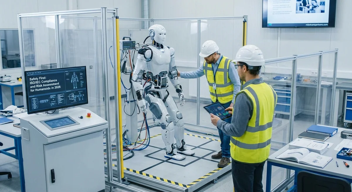
Humanoid robots are becoming more common in factories, homes, and stores. These robots range from Boston Dynamics’ Atlas (a walking demo robot) to Tesla’s Optimus (planned for volume production by 2026) (www.automation-next.com). As machines enter spaces shared with people, safety must come first. International standards help guide designers and users through risk assessment and safety measures. For example, ISO 12100:2010 (Safety of machinery) lays out a systematic risk assessment and risk reduction process (www.iso.org). A recent robotics safety guide explains that risk assessment must define the robot’s use, its workspace and life cycle, then identify hazards (things that could hurt someone), estimate the risk (likelihood and severity), and apply measures to reduce risk (link.springer.com) (www.plcacademy.com). It emphasizes an iterative approach: after adding safety measures, re-check hazards to ensure risks are low (link.springer.com) (www.plcacademy.com).
Conducting a Formal ISO 12100 Risk Assessment
Step-by-step risk assessment per ISO 12100 includes:
- Define boundaries and usage. First decide how, where and when the robot will operate. Specify tasks, environment, number of operators, and usage limits (link.springer.com).
- Identify all hazards. List anything that could cause harm: moving parts, pinch points, electrical sources, software errors, falling loads, etc. Many methods exist (e.g. FMEA, HAZOP) to find hazards systematically (link.springer.com) (www.plcacademy.com).
- Estimate risk level. For each hazard, estimate how severe an injury could be and how likely it is to occur. ISO 12100 and ISO/TS 14121 suggest scoring hazards on severity and frequency to find the most critical risks (www.iso.org) (www.plcacademy.com).
- Reduce risk by design. The first goal is to eliminate hazards or shape the design to avoid danger. For example, guard a crushing point or limit the robot’s speed. Apply inherently safe design when possible.
- Implement protective measures. If hazards remain, add safeguards like guards, sensors or safety systems (see next sections).
- Re-evaluate. After each change, go back and check all hazards again. The process is iterative: adding one safety feature can introduce a new risk (e.g., electrical guard cables requiring a safe disconnect), so the loop repeats until risks are “as low as reasonably practicable” (link.springer.com) (www.plcacademy.com).
Every major claim here is backed by ISO 12100 principles and robotics safety research (www.iso.org) (link.springer.com) (www.plcacademy.com).
Integrating Functional Safety: PL and Power/Force Limiting
Humanoid robots often use safety-related control systems. The reliability of these systems is measured by a Performance Level (PL). PL (rated a through e) indicates how well a safety function (like an emergency stop) will perform under fault conditions (www.keyence.eu). For each safety function, a required PL (called PLr) is determined based on risk factors: how serious a potential injury is, how often exposure occurs, and how avoidable the hazard is (www.keyence.eu). The actual system must meet or exceed that required PL (for example, a very high-risk function might need PL d or e). In practice, engineers use standards like ISO 13849 or IEC 62061 to calculate PL based on components (circuit reliability, diagnostics, etc.). (In U.S. terms this is similar to choosing a Safety Integrity Level (SIL) in IEC 61508/62061.)
Another key concept is Power-and-Force Limiting (PFL). PFL is a strategy for robots designed to touch or bump people without deadly harm. It means limiting the robot’s mass and speed so any contact won’t cause serious injury. For example, a humanoid elevator might use low-powered actuators and pressure-sensitive skins, or software limiting torque and speed to safe values. PFL is explicitly mentioned in collaborative robot standards (ISO/TS 15066) and tested during validation (roboticsystemsauthority.com). In validation tests (see below), designers verify that collisions result in forces below injury thresholds, as a final safety check (roboticsystemsauthority.com).
Safeguarding Strategies
Several practical safeguards ensure humans stay safe around humanoids:
-
Speed-and-Separation Monitoring. Sensors (such as LiDAR, cameras, or proximity scanners) watch for humans near the robot. If a person enters a watch zone, the robot automatically slows or stops. This method is defined in ISO TS 15066 for collaborative operations. For example, an advanced human-aware robot might use an overhead camera to compute a minimum safe distance, then apply the ISO/TS 15066 safety equation to slow the robot before a collision (www.nist.gov). Researchers confirm that implementing speed-and-separation monitoring per ISO standards dramatically reduces collision risk (www.nist.gov).
-
Geofencing. A geofence is an invisible boundary that a robot will not cross. Many mobile humanoid robots or delivery robots use this: for instance, a robot cart may have GPS or ultra-wideband sensors that define a “keep out” zone (like stairs or customer areas). When the robot approaches the fence, it transitions to a safe mode or turns around. Geofencing is often not a formal ISO requirement but is a practical layer of safety engineering for mobile robotics.
-
Emergency-Stop Architecture. Every robot cell must have one or more emergency-stop (E-stop) buttons to cut power instantly. ISO 13850 (and its legacy EN 418) requires E-stop functionality with certain categories of stop. Category 0 stop cuts power immediately (an uncontrolled stop), while Category 1 stops in a controlled way then cuts power (www.se.com). Humanoids should support at least one emergency-stop circuit at Category 0 or 1. Best practice is to physically test every E-stop before each shift. In fact, audits highlight that many accidents come from unverified E-stops and sensors (oxmaint.com). Industry guidance says: “Emergency stop devices on industrial robots must be physically tested at every shift start — not just visually inspected. ISO 13850 and ANSI/RIA R15.06 require it.” (oxmaint.com). In short, every E-stop button should immediately trigger the safe-stop logic, and the system must log or indicate the stop event.
Each of these strategies should be combined. For example, you might have physical guards (walls or light curtains) in addition to software slow-down. Many robotic cells use light curtains or scanners to enforce the speed/separation concept. In any case, all wiring and logic for these devices should follow safety-rated control categories (e.g. dual channels, self-checking relays) per ISO 13849 or IEC 62061, ensuring a low chance of failure.
CE Marking and Comparable Certification
To sell a robot in the EU or similar markets, manufacturers must meet safety directives and affix a CE mark. A humanoid robot would fall under the EU Machinery Directive (2006/42/EC) and possibly other directives (EMC, Low Voltage, etc.). CE marking requires a Technical File documenting compliance. At minimum, the Technical File should include: the risk assessment, essential safety requirements met, test reports, and user documentation (www.certifico.com). For example, one technical file template lists Risk Assessment, Essential Requirements (Machinery Annex I), risk evaluations per relevant EN standards, CE Declaration of Conformity, safety test reports (e.g. EN 60204-1 electrical safety test), and the instruction manual (www.certifico.com). The manufacturer (or system integrator) must sign a Declaration of Conformity stating the robot meets all applicable standards.
Outside Europe, comparable certifications exist. In the U.S., robots are often validated to ANSI/RIA R15.06 (based on ISO 10218) and may carry UL listings. The UL 1740 Standard for Robots covers safety requirements in North America. A recent guide notes that CE certification generally relies on EN ISO 10218 and EN ISO 13849, whereas North American UL certification refers to UL 1740 and UL 3100 (www.jqrtest.com). (UL 3100 is a newer standard for specific robotic equipment.) In China, the GB/T robot standards (CR certification) apply. In practice, a global manufacturer often prepares similar technical documentation keyed to each region’s standards. For example, a Chinese certification matrix shows CE (EU) requires ISO 10218/13849, UL (USA) uses UL 1740/3100, etc. (www.jqrtest.com). Ensuring dual compliance may involve meeting both ISO and ANSI guidelines.
Validation and Verification Approaches
After design and integration, thorough testing is critical. Verification and validation are two related steps. Verification checks that the robot was built correctly to spec; validation checks that the correct system was built for the intended use (roboticsystemsauthority.com). In robotics, ISO itself notes both concepts (ISO 9283, though for performance) and good practice is clear: you must verify all safety functions (did we wire category-2 stops correctly?) and validate them in realistic scenarios (will the robot actually stop if an operator steps in?).
A structured validation plan typically follows the development lifecycle: define test criteria, test sub-assemblies, then do system acceptance. In safety-critical systems, this includes Safety and Hazard Validation (roboticsystemsauthority.com). For example, one framework states: when validating the final robot system, the risk assessment drives the test cases. You explicitly test protective stops, speed/separation safeguards, power/force limiting responses, and other safety behaviors (roboticsystemsauthority.com). In practice, this means intentionally triggering hazards to ensure the robot responds safely: for instance, placing a safety dummy or mannequin in reach to verify the robot slows or stops. Large workpieces or sandbags might be used to test collision forces. Any deviations (e.g. a stop taking too long or a sensor gap) must be corrected before deployment.
In autonomous or AI-enabled robots, additional validation is needed. Our sources note that if machine learning software is involved, one must do distributional testing and monitoring after deployment (roboticsystemsauthority.com). However, for most industrial humanoids today, safety is achieved by deterministic controls combined with conservative safeguards. Documentation of all V&V steps — e.g. test reports, incident logs, certificates — becomes part of the compliance record.
Pre-Deployment Safety Checklist
Before letting humans into the robot’s workspace, a final safety audit is wise. A pre-deployment checklist ensures nothing is overlooked. Key items include:
- Inspect physical guards and barriers. Verify all fences, enclosures and interlocks are installed as per design. Ensure any light curtains or scanners have unobstructed view.
- Test emergency stops and safety circuits. Press every E-stop button and verify the robot stops immediately (Category 0 or 1, as intended) (www.se.com) (oxmaint.com). Check that the controller logs or flashes a fault when E-stop is pressed, and that the system can restart correctly afterwards.
- Verify sensors, switches, and PLC logic. For speed/separation systems, simulate a person entering the zone: does the robot slow/stop as programmed? Check safety-rated inputs (like guard door switches) for correct function.
- Check robot joint limits and brakes. Ensure software speed/torque limits are set. Test that power is cut if a joint drive fails (brake engagement). Mechanical inspections (looseness, wear) should match manufacturer guidance.
- Review documentation and labels. Confirm the instruction manual, warning labels, and maintenance procedures are present. Any local regulations (e.g. OSHA notices) must be posted.
- Ensure training. Operators and maintenance staff should have completed required safety training for that robot model and their tasks.
A recent industry checklist stresses this: many accidents happen because safety audits are skipped (oxmaint.com). For instance, an automated audit toolmaker found that most robot cell incidents in factories were traced back to “unverified emergency stops” and “breached safety zones” in routine checks (oxmaint.com). Performing a walkthrough with this list lets integrators catch any oversights.
Commissioning Plan
When commissioning the robot system, proceed in stages:
- Dry Run/Test Mode. Run the robot through its tasks at low speed without live loads. Check that the control software follows the planned movements and that safety stops trigger under simulated fault conditions.
- Incremental Load Increase. Gradually increase speed and payload, verifying that force and pressure remain within safe limits when humans are nearby. Calibrate any force sensors or power limits as needed.
- Documentation of Tests. Record each safety test (E-stop result, collision simulation, sensor activation). Compare against design requirements. Any failure requires a revisit of design or controls.
- Training and Procedures. Before go-live, train end-users on emergency procedures and safe operation. Review the safety doors and emergency protocols with on-site staff. Create a maintenance schedule for safety components.
- Final Approval. A responsible engineer (often the integrator or safety officer) should sign off that all safety tests passed. The complete safety dossier (risk assessment, test logs, certificates, manuals) should be compiled and retained.
Throughout commissioning, one key endorsement is to follow the risk assessment itself. The earlier analysis of hazards should be revisited with each test. Standards imply that re-validation is needed after any hardware/software change (roboticsystemsauthority.com). For example, if a sensor field-of-view is adjusted, redo the human-approach test. In short, the risk assessment drives commissioning tests and helps define when safety is sufficient.
Conclusion
By 2026, humanoid robots will increasingly move among people. Safety standards and careful engineering practices are essential to prevent accidents. A formal ISO 12100-based risk assessment, combined with functional safety design (PL ratings) and collaborative safeguards (speed-limits, E-stops), will form the foundation of any safe system. With thorough documentation and testing, integrators can achieve CE marking (in Europe) or UL certification (in North America) while ensuring operators and bystanders stay protected. A final site checklist and step-by-step commissioning plan turn paper plans into real-world safety. In this way, safety-first engineering lets both business and consumers benefit from humanoid robots without unnecessary risk (link.springer.com) (www.certifico.com).
Never Miss a Robot Breakdown
Get deep research, head-to-head robot comparisons, and industry analysis delivered straight to your inbox — multiple times a week, completely free.